DirectIP SBD Information #
1.1 Purpose
1.2 Definitions
1.3 Acronyms
2.0 DirectIP: Functional Description
2.1 Advantage of DirectIP
2.2 MO DirectIP Transfers
2.3 MT DirectIP Transfers
3.0 Applications Requirements for MO and MT DirectIP
3.1 MO DirectIP Server/Client Requirements
3.2 MT DirectIP Server/Client Requirements
4.0 Specifications for MO and MT Messages
4.1 Complete Message Structure
4.2 Message Length
4.3 Byte Alignment
4.4 Information Elements
4.5 Information Element Identifiers
4.6 Information Element Length
4.7 Information Element Parsing
4.8 A Valid MO Byte Stream After a Successful SBD Session
4.9 An Invalid MO Byte Stream After an Unsuccessful SBD Session
4.10 MT Message Byte Stream and Potential Confirmation
5.0 Specifications for Information Elements
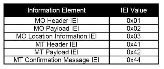
5.1 Information Element Identifiers
5.2 MO DirectIP Header
5.3 MO Payload
5.4 MO Location Information
5.5 MT DirectIP Header
5.6 MT Payload
5.7 MT Message Confirmation Message
1.0 INTRODUCTION – DirectIP SBD Information
1.1 Purpose
This document can be used as a source of specifications for implementing the DirectIP service; however, this document can also serve the purpose of providing customers with details of DirectIP operation between the Gateway Short Burst Data (SBD) Subsystem and the software application in control of the Iridium Subscriber Unit (ISU). An ISU can be any of the NAL Research’s Iridium modem or tracker. Mobile Originated (MO) and Mobile Terminated (MT) SBD messages are exchanged via the socket-based delivery provided by DirectIP. DirectIP allows a direct connection to a distant IP address for the delivery and reception of the MO and MT messages.
The detail of this document will be restricted to the interfacing between the vendor application controlling the ISU and the Gateway SBD Subsystem (GSS). Details of the processing done within the Gateway will not be provided here.
1.2 Definitions
Message – The complete data transfer between the vendor application and GSS including a header, optional sets of information, and the payload to be transmitted over the air.
Payload – The actual data to be transmitted over the air.
1.3 Acronyms
| CDR | Call Detail Record |
| CRC | Cyclical Redundancy Check |
| DB | Database |
| DSC | Delivery Short Code |
| DSD | Data Set Download (aka DSDR) |
| DSDR | Data Set Download Response (aka DR) |
| DSS | Diagnostic System Services |
| DTE | Data Terminal Equipment |
| ECS | ETC Communications Sub-system |
| ETC | Earth Terminal Controller (ETC consists of ECS, ETS & ESS) |
| ETS | ETC Transmission Subsystem |
| FA | Field Application |
| GBS | Gateway Billing Subsystem |
| GEO | Geographical (as used in ‘geographical location’) |
| GIE | Gateway Infrastructure Equipment |
| GSM | Global System for Mobile Communication |
| GSS | Gateway SBD Subsystem |
| GW | Gateway |
| IE | Information Element |
| IEI | Information Element Identifier |
| IMEI | International Mobile Equipment Identifier |
| IP | Internet Protocol |
| ISU | Iridium Subscriber Unit (NAL Research’s modems and trackers) |
| LBT | L-Band Transceiver |
| MO | Mobile Originated |
| MOM | Mobile Originated Message |
| MOMSN | Mobile Originated Message Sequence Number |
| MT | Mobile Terminated |
| MTM | Mobile Terminated Message |
| MTMSN | Mobile Terminated Message Sequence Number |
| SBD | Short Burst Data |
| SEP | Short Burst Data ETC Processor |
| SPNet | Iridium Service Provider Network Provisioning Tool |
| SPP | Short Burst Data Post Processor |
| VA | Vendor Application |
2.0 DirectIP: Functional Description
2.1 Advantage of DirectIP – DirectIP SBD Information
The advantage DirectIP has over the existing e-mail protocol is the efficiency with which DirectIP transfers SBD between the Iridium Gateway and client applications and smaller latencies. DirectIP is comprised of a specialized socket-oriented communications protocol which uses direct connections between the Iridium Gateway and the client applications.
The DirectIP protocol consists of separate Gateway components for the transfer of MO and MT messages. The interaction can be likened to client/server architecture. The MO and MT DirectIP protocols utilize bi-directional TCP/IP socket connections.
2.2 MO DirectIP Transfers – DirectIP SBD Information
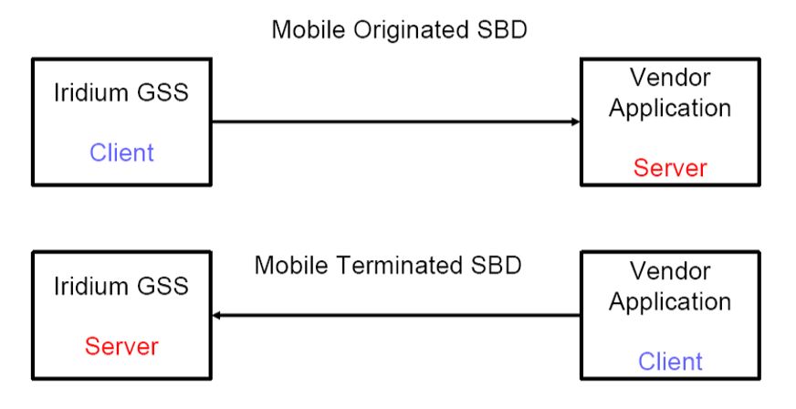
In the case of MO messages the vendor application plays the role of a server application. For MO messages the Iridium Gateway seeks to establish a connection with the vendor application for MO transfers. In this case an attachment is only made by the Gateway to the vendor application when data is being delivered by the Gateway.
The MO DirectIP protocol will only transfer MO messages from the Iridium Gateway (client) to the vendor application (server). No acknowledgment is expected from the server in the MO DirectIP protocol.
When a number of messages are sent to the same ISU they are stored and delivered in first-in-first-out order; however, only one message is delivered per socket connection. When the first message in the FIFO queue is delivered the remaining messages move up in position toward the first position or front of the queue.
When an ISU initiates a session between itself and the Iridium Gateway to send out a MO message the Gateway stores the message in the queue. Upon reception of this message the Gateway opens a socket, connects to the client application, and then transfers the MO message which includes SBD session descriptors. The socket is then closed and the aforementioned process is repeated for any other messages in the queue.
Each client application may have up to 1000 messages in its provided queue at the Gateway at any given time. In the case of an exceeded message limit the oldest messages will be deleted.
If the first attempt to connect to the client times out the message delivery will not take place. Additional attempts will be made with the timeout values for the first, second, and third attempts being 5, 15, and 45 seconds respectively. Following the third attempt, attempts to connect will continue using the previously mentioned timeout values. This will continue up to the lifetime of the message which is 12 hours from the time it is received at the Gateway. Each message has a lifetime of up to 12 hours starting at the time the payload arrived at the GSS. If it cannot be delivered it will be deleted from the queue.
2.3 MT DirectIP Transfers – DirectIP SBD Information
For MT message transfers the MT DirectIP component plays the role of server while the vendor application plays the role of client in a server/client architecture. In this case the MT component of the Gateway listens for connections from the vendor software for the purpose of transferring MT messages.
The MT DirectIP protocol will only transfer MT messages from the vendor application (client) to the Iridium Gateway (server). The MT DirectIP protocol calls for a confirmation to be sent from the server back to the client; the confirmation will indicate success or failure of data processing.
When the vendor application wishes for a message to be queued, the application opens a socket and connects to the Iridium Gateway server, the message is then delivered with disposition. The Iridium server parses the received message and inserts the payload into its database. Afterwards a confirmation is sent back to the client application.
After the payload is deposited a separate process in the Iridium Gateway queues the payload for transfer while assigning a Mobile Terminated Message Sequence Number to each payload. The payload in the front of the queue is marked as “Pending” and the others are marked as “Queued”.
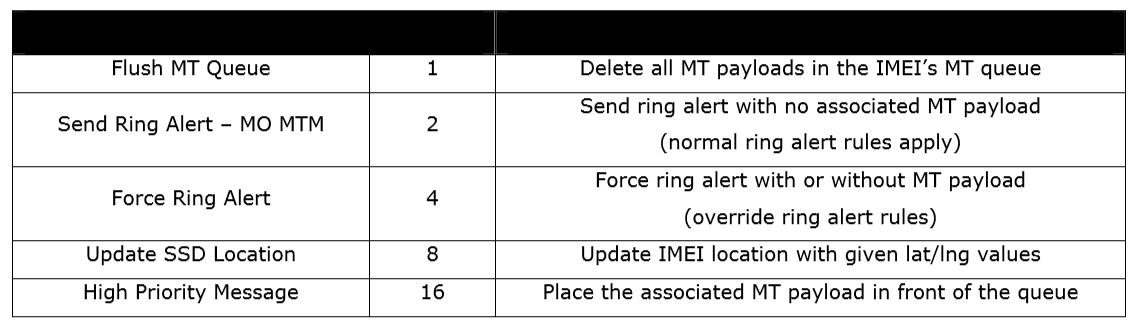
The added MT delivery features are only available with the use of the MT DirectIP protocol. The MT disposition field in the MT header is a 2-byte bit map that provides the availability of 16 flags.
There is a Flush MT Queue flag that enables an application to delete all of the messages in the MT Queue at the Gateway except for the current payload that arrived with the set MT Queue flag.
There is also a Send Ring Alert with no MT payload flag. When set, this flag causes the GSS to send a ring alert to the given IMEI within the bounds of normal ring alert processing. The bounds include the ISU’s ring alert enable flag and the ISU’s attach/detach status. If the ISU is attached and its ring alerts are enabled, a single alert will be sent. If either of these conditions fails to be met the vendor will be made aware, through a status flag in the confirmation message, that no ring alert will be sent. If a MT payload is included with the ring alert from the GSS the MT-SBD transfer will result in a protocol error. If a ring alert is sent from the GSS and there is an awaiting payload in the queue, that payload will not be delivered until the ISU retrieves the MT-SBD message. The functionality provided by this feature should not be used to check the power status of ISUs or to compensate for poor application design. Using this command for those purposes may result in the implementation of restrictions. Instead the application should utilize the +SBDI command with an empty send buffer for those purposes.
3.0 Application Requirements For MO and MT DirectIP
3.1 MO DirectIP Server/Client Requirements MO Gateway Client Requirements – DirectIP SBD Information
• The client must seek to establish a TCP/IP socket connection to the IP address and port number provided for the originating ISU.
• After a connection is established the client will transfer the MO payload and close the connection.
• If a connection is failed to be established the client will follow the retry protocol described above in Section 2.2 paragraph 6.
• After successful transmission the client will close the socket connection and will not expect an acknowledgment from the server.
MO Application Server Requirements
• The server will listen for TCP/IP socket connections on a specific port.
• Once connected, the client will transmit the MO payload and the server will receive the message in its entirety before parsing.
• The server will allow the client to close the socket connection.
3.2 MT DirectIP Server/Client Requirements MT GSS Server Requirements – DirectIP SBD Information
• The server will listen for TCP/IP socket connections on a specific port.
• Once connected, the server will receive the entire MT message before parsing.
• The server will validate the message to ensure it meets these criteria:
1. IMEI is valid and provisioned.
2. Input in MT header is valid.
3. Payload does not exceed maximum for ISU (270 bytes for 9601 IMEIs and 1890 for 9522[A]s).
4. Gateway resources are available.
• The server will send a confirmation indicating success or failure.
• The server will terminate the socket connection after transmission of confirmation message.
• If the connection fails at any time prior to transmission of confirmation, the MT message will be dropped.
MT Application Client Requirements
• The client will seek to establish a TCP/IP socket connection to the IP address of the Gateway MT DirectIP server on a specified port.
• Once connected, the client will transmit the MT payload and wait for the confirmation.
• Once the confirmation has been received, the client will allow the server to close the socket connection.
4.0 Specifications for MO and MT Messages – DirectIP SBD Information
4.1 Complete Message Structure
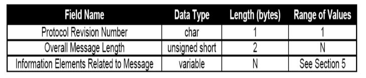
The application receiving a message will receive three bytes. A DirectIP protocol revision number, the number of bytes that make up the body of the message, and the number of information elements that the message is made of. The table below summarizes in detail.
4.2 Message Length
The value of the message length flag indicates the number of bytes that make up the body of the message after the initial three bytes.
4.3 Byte Alignment
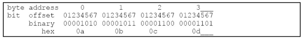
The entirety of the message will be seen as a byte stream. Multi-byte fields are transmitted in network byte order (big endian). An example of the 4 byte field 0x0a0b0c0d is given below.
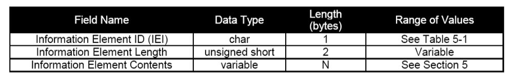
4.4 Information Elements
Information elements are segments of the transmitted data. These segments allow maximum flexibility while using the protocol. Existing information elements are shown below. The format of each information element is the same as the table below.
4.5 Information Element Identifiers
Every information element starts with 1-byte of data which is the information element identifier. The IEI uniquely defines the next 2+N bytes. A list of the IEs and their IEIs is shown below.
4.6 Information Element Length
Following the IEI are two bytes that give the length of the IE in bytes following the first three bytes of the message. This two byte field is used for uniformity across all information elements. This uniformity in all IEs allows for new information elements unrecognized by an application to have their length read and that length skipped so the unrecognized IE is ignored.
4.7 Information Element Parsing
A message will be parsed after it has been received in its entirety. The message will consist of the IEI, two bytes representing the number of bytes in the IE, and the IE following the two bytes giving its length. The interpretation of the bytes is dependent upon the IEI. Oversized or undersized messages, determined by the parser, will be dropped. For MT DirectIP processing an error will be returned in the confirmation.
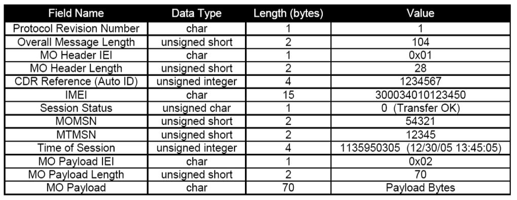
4.8 A Valid MO Byte Stream After a Successful SBD Session
The table below is the byte stream for a MO DirectIP message after it has been received at the Gateway (before it is sent to the application). Notice that the IMEI has been configured to not include the geolocation.
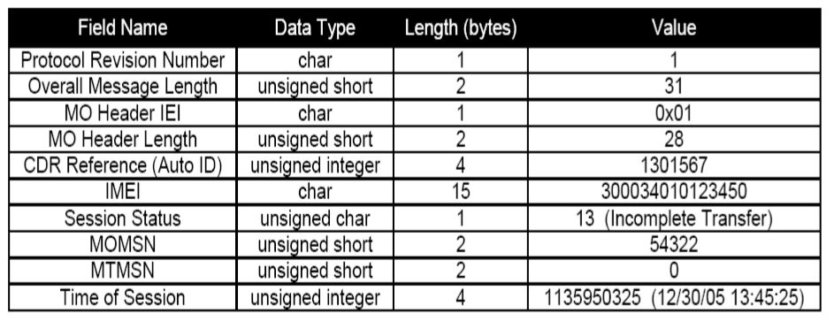
4.9 An Invalid MO Byte Stream Following an Unsuccessful SBD Session
The table below illustrates an invalid byte stream after an unsuccessful SBD session due to an incomplete transfer; the payload has not been included.
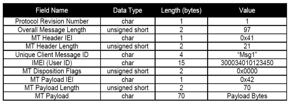
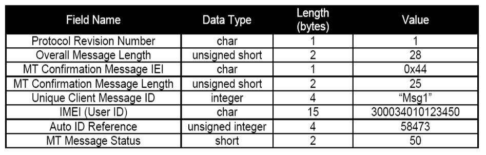
4.10 MT Message Byte Stream and Potential Confirmation – DirectIP SBD Information
The following shows an example byte stream and response. The example assumes the IMEI had 49 MT messages queued. The maximum number is 50.
5.0 Specifications for Information Elements
5.1 Information Element Identifiers – DirectIP SBD Information
The following table lists all of the information elements. Note there is no guarantee that the elements will appear in any order in the message.
5.2 MO DirectIP Header – DirectIP SBD Information
The information in the MO DirectIP Header is mandatory for every DirectIP MO message. The header is detailed in the following table.
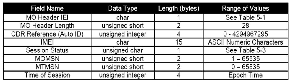
MO Header Length
MO Header Length specifies the size of the IE in bytes. Although the length is fixed MO Header Length is a standard for all IEs. This standardization gives flexibility for future IEs.
CDR Reference
Also referred to as the auto ID, this is a unique value given to each call data record to guarantee the ability to reference an individual call.
IMEI
The IMEI is unique to each ISU. In this case it is the IMEI of the ISU that sent the MO message. It is always 15 characters long.
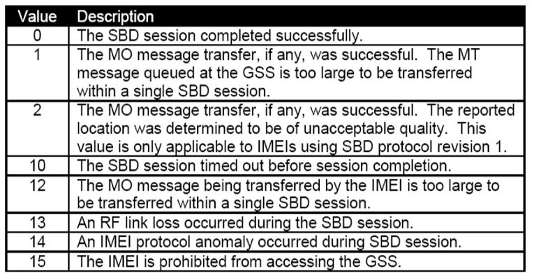
Session Status
The Session Status indicates success or failure of the SBD session between the IMEI and the Gateway. No payload will be present in MO messages for which the status is unsuccessful. The table below gives descriptions for the session status values.
MOMSN
The mobile-originated message sequence number associated with the SBD session. This value is set by the IMEI. The MOMSN is transmitted to the Gateway during every SBD session. The MOMSN is incremented for every successful SBD sessions.
MTMSN
The mobile terminated message sequence number associated with an SBD session. Unlike the MOMSN which is set by the IMEI, the unique MTMSN is set by the Gateway when the message is queued for delivery. The MTMSN is transferred to the IMEI as part of the MT payload transfer regardless of an SBD session’s success. The value of MOMSN will be zero if there is no MT delivery attempt. This is unique to each IMEI.
Time of Session
This is a UTC timestamp in the form of an epoch time integer. The timestamp is the time of the session between the IMEI and the Gateway. The epoch time represents the seconds since the start of the epoch: 1/1/1970 00:00:00. Format: epoch time integer Resolution: 1 second
5.3 MO Payload
This is the actual MO payload from the IMEI currently at the Gateway. The accompanying payload is a result of the successful SBD session identified in the header. In an MO message delivery related to an empty mailbox check (EMBC) session or a failed session, no payload will be included.
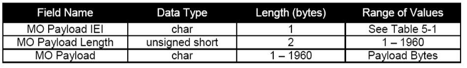
MO Payload Length
The MO Payload Length is the number of bytes in the MO payload.
MO Payload
The MO Payload field is the data of the MO payload. The size of the MO payload is restricted to 340 bytes for the 9601 series and 1960 bytes for the A3LA series.
5.4 MO Location Information
This IE includes location values that are an estimate of the location of the IMEI from which the message originated. The MO Location Information field is optional for MO messages; the option is determined when the IMEI is configured but can be changed at a later time. To do this please send an email to NAL Research with the IMEI number and request that Location information be added or removed. If using encryption with the 9601-DGS it is recommended that the location element be removed. The CEP radius is the radius around the center point within which the unit is located. Although the resolution of the reported position is given to 1/1000th of a minute, the accuracy is limited to within 10Km 80% of the time.
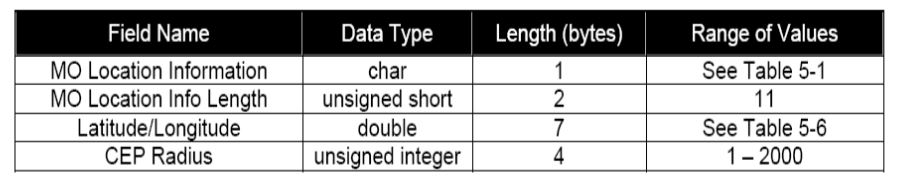
MO Location Information Length
The MO Location Information Length field specifies the number of bytes in the information element following the MO Location Information Length byte.
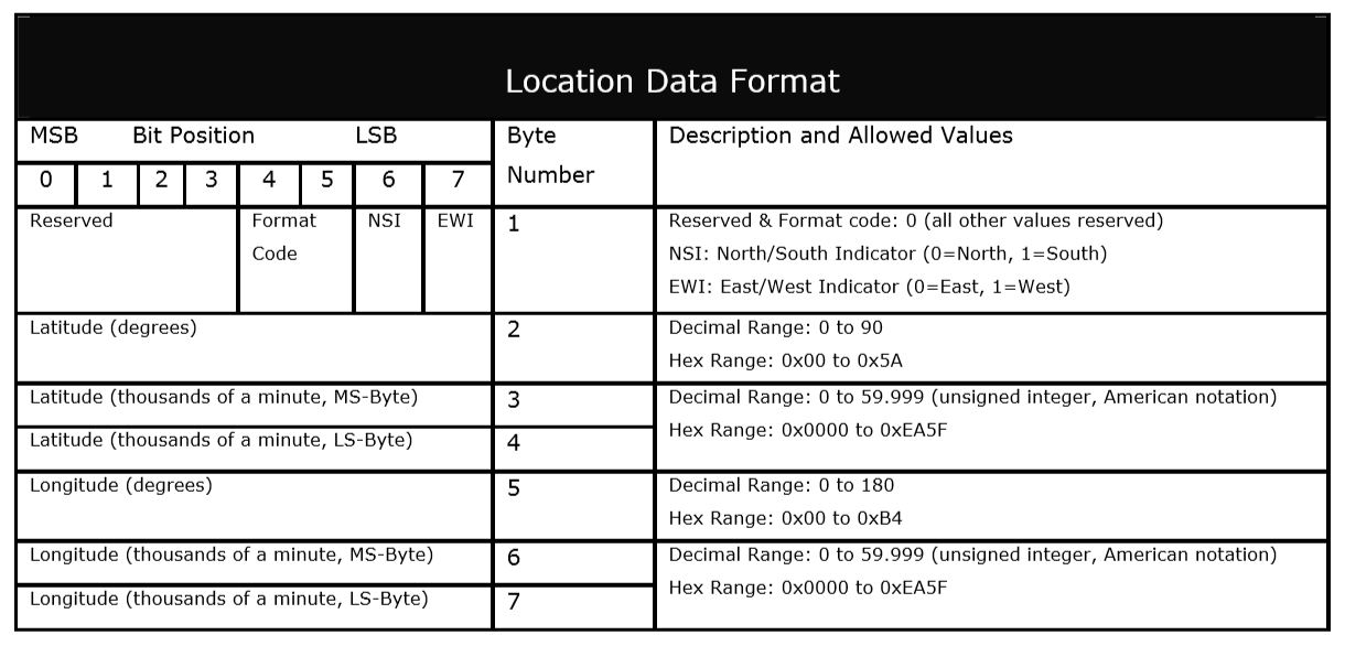
MO Latitude and Longitude
These two fields provide a center point from which the location is estimated. The fields are derived from the LGC coordinates output from the CPLD exchange during the SBD session.
CEP Radius
The CEP Radius gives the radius in kilometers around the center point within which the IMEI is located. The probability of accuracy is 80% within 10km and resolution is 1km.
5.5 MT DirectIP Header
The MT Direct IP Header field is the mandatory header information that is a part of every DirectIP MT message delivery.
MT Header Length
This particular field specifies the number of bytes in the IE following the MT Header Length byte. Although the length is fixed, this field is a standard across all IEs to allow for flexibility for future enhancements.
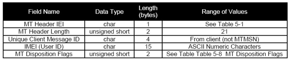
Unique Client Message ID
Within the vendor client’s own application will be a unique 4-byte message ID. The Gateway server will only use this value to include in the confirmation message sent back to the client. This ID should serve as a form of validation and reference for the client application. Although the data type is specified as chars, from the client’s point of view the data type may differ.
IMEI
The International Mobile Equipment Identifier is a unique number to each ISU. The 15-digit ASCII formatted number specifies the destination IMEI of the MT message.
MT Disposition Flags
Each of these flags is set by the vendor client to trigger some action to be performed by the Gateway. Different combinations of flags are permissible. The 2-byte bit map provides for the availability of 16 flags. Existing flags are shown below. Detailed description was given above.
5.6 MT Payload
This is the actual data that will be queued and delivered to the destination IMEI. The inclusion of the IE in the MT delivery is optional depending on the disposition flags included in the header.
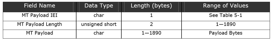
MT Payload Length
The MT Payload Length field indicates the number of bytes in the MT payload.
MT Payload
This is the actual content of the MT payload. The MT payload size is restricted to 1890 bytes for A3LA transceivers and 270 bytes for 9601 transceivers.
5.7 MT Message Confirmation Message
This is the confirmation message sent to the vendor client from the Gateway that will indicate success or failure of the message processing. A confirmation will be sent for every MT message received by the Gateway.
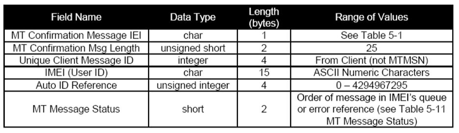
MT Confirmation Message Length
The MT Confirmation Message Length field Specifies the number of bytes in the IE following the MT Confirmation Message Length byte. Although the length is fixed, this field is included as a standard across every IE. This allows for flexibility in future enhancements.
Unique Client Message ID
The Unique Client Message ID field is a unique information element sent as part of the MT header in the message transferred to the Gateway. The intent of this field is for it to serve as a form of validation and reference for the client application.
IMEI
The International Mobile Equipment Identifier is unique to each ISU. It is a 15-digit ASCII formatted number that identifies the destination ISU of the MT message.
Auto ID Reference
The Auto ID Reference allows the capability of referencing a unique MT payload with the SBD database. The ID is assigned at the time the payload is inserted into the database as a new record, but prior to the record being queued for delivery and the MTMSN is assigned. This reference is sent instead of the MTMSN in order for the Gateway server to remain separate from all other GSS processes and to allow the socket connection to be closed as soon as possible. In the event of an error while processing the message this value will be zero.
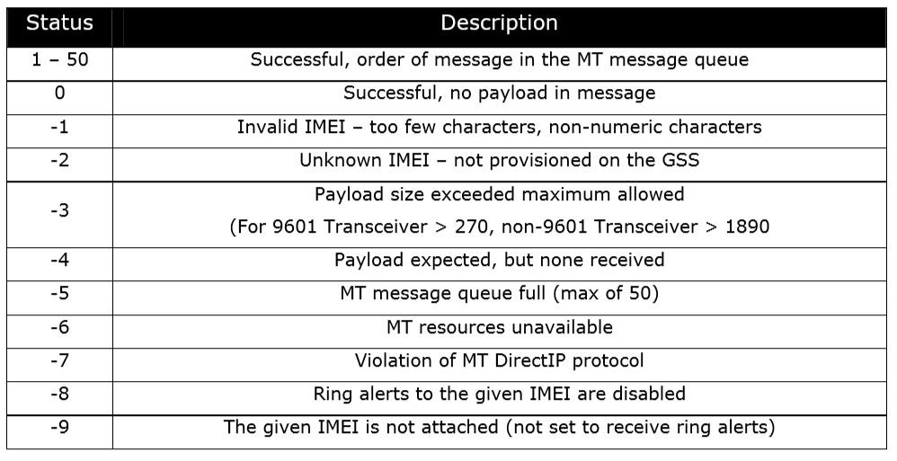
MT Message Status
The MT Message Status is the value returned with every confirmation. The value indicates that the overall MT message was received and validated and whether the payload was queued successfully or a failure occurred. Provided the payload was queued successfully the value will be a positive number indicating the order of the received payload in the IMEI’s associated MT message queue. If the payload was not successfully queued the value will be a negative number which will serve as an error code specifying the detected problem. The table below shows the possible status values including the error codes. The last two error values (-8 and -9) only apply when the “Send Ring Alert” disposition flag has been set.